De
De  Fr
Fr  Pt
Pt  En
En 

Floor Plan
 Ribbon: 3DScan – Features >
  Floor Plan
Menu: 3DScan – Vectorization >  Floor Plan
Toolbar: Features 3DScan >  FloorPLan
 Command line: PC_FLOOR_PLAN
Creating a vector floor plan from point cloud data. A point cloud can consist of an exterior scan of a building and scans of its interior.
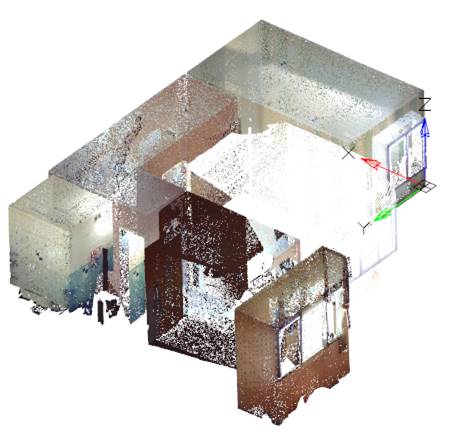
The command opens the Floor plan dialog box.
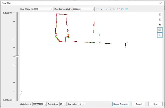
The dialog allows you to configure the parameters of the point cloud section performed at a specified level from the earth surface, and to vectorize it.
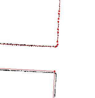
The preview window displays the point cloud section, which was obtained as a result of the specified settings. The window allows you to zoom, pan the image and work with the vector geometry previously recognized in the section.
Options:
|
Slice width: |
The width of the cloud cross-sections (layers) to be vectorized. Excessive section width can lead to noise and thickening of contours, to the appearance of unnecessary contours and distortion of the topology, as a result of excess cloud points getting into the section. Insufficient width makes the contours thin and discontinuous due to the lack of cloud points falling into the section. |
|
Min. opening width: |
Min. opening width is a parameter that affects the combination of vectors during vectorization. If the specified distance is less than the Minimum Width value, then the vectors will be combined into one, if greater, then the gap will be taken into account. |
|
Vertical slider |
The level from the ground at which the point cloud is cut. Section plane is parallel to the XY plane of the current UCS and perpendicular to the Z axis of the current UCS |
|
|
Allows you to create a vector segment by specifying two arbitrary points. In the preview window, specify the start and end point of the segment. The segment is created for the current section. |
|
|
Allows you to split a vector segment in the specified location. |
|
|
The mode to change the lengths of vector segments. With the button pressed, you can move the vertex of any segment along its length. To exit the mode, release the button. |
|
|
Connects the ends of preselected segments. The button becomes active when two or more vector segments are selected in the preview window. |
|
|
Allows you to delete selected vectors. |
|
|
Allows you to set the floor height. |
|
|
Allows you to set the ceiling height. |
|
|
Resets the height. |
|
|
Manages zoom in and out, resets zoom. |
|
|
Manages the display of rasters in the preview window. |
|
|
Manages the display of vectors in the preview window. |
|
|
Loads recognized data into the drawing. |
|
Go to height |
Regulates the height of the cross-section. |
|
Count steps |
The number of cloud cross-sections, displayed as horizontal bars near the scale. |
|
Hold radius |
The parameter specifies the vector search radius in pixels. |