De
De  Fr
Fr  Pt
Pt  En
En 

Fit Plane
 Ribbon: 3DScan – Features >
  Fit Plane
Menu: 3DScan – Features >  Fit Plane
Toolbar: Features 3DScan > Fit Plane
 Command line: PC_FIT_PLANE
The command creates the plane (region object) fit into the cloud/section.
The command options are set in the Extended Properties bar.

|
Geometry |
Type of created object. |
|
Data source |
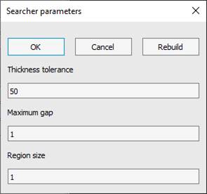
Point clouds: geometry is generated in two ways: 1. The user selects an area containing points, and the program immediately attempts to construct an object and display a preview. The Searcher parameters panel opens, allowing you to refine the selection parameters for greater accuracy:
· Thickness tolerance — maximum deviation of points from the geometry · Maximum gap — search step/distance between points · Region size — radius of the search area from the geometric center of the initial selection 2. The user selects one or more points from which the search will begin. A preview of the object will not appear until the points necessary for construction are found or selected.
Points: geometry is constructed exclusively from the selected points. The program does not analyze the entire cloud; the user controls which points are included in the construction (the points may be scattered and unconnected). |
|
Threshold distance |
The maximum deviation of the point cloud’s positions from the ideal. That is, the spread of coordinates that can be ignored in order to consider the points as belonging to a single line, surface, edge, etc. The threshold distance should be greater the less accurate the scan is and the worse the object’s surfaces and edges are expressed. However, if the threshold distance is increased excessively, the likelihood of inaccurate plane placement increases. |
|
Draw solid |
Specify whether the plane should be created in this command session, or whether the command was called only to change its parameters. Important! The plane is constructed based on the most prominent points on each of the four sides of the contour. To obtain a more "fitted" plane, it is recommended to use the Draw convex edges option. |
|
Number of iterations |
The number of iterations for determining the plane's size and position. A higher value increases calculation time but also improves the likelihood of finding the correct size and location. The parameter value must be greater than 0. |
|
Draw convex edges |
Specify whether a convex edges should be created in this command session, or whether the command was called only to change its parameters. |
After the parameters are selected, the program will prompt you to execute the command.
Once the geometry is constructed, the program will provide a report based on the selected data source.
· Point clouds:

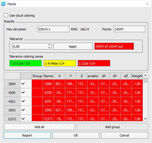
This window displays the maximum deviation among all points, the root-mean-square (RMS) deviation (or overall construction accuracy), and point information.

· Points:

The command allows you to select a group of points for surface construction analysis.
The point list can be modified; any point can be removed from or included in the calculations. If the checkbox next to a point number is selected, that point is used to calculate the surface parameters. If there is no flag, then the deviations from the surface (that constructed using the working points) are calculated for this point.
If you disable cloud coloring, you can separately configure the tolerance and color-coded tolerance zones.